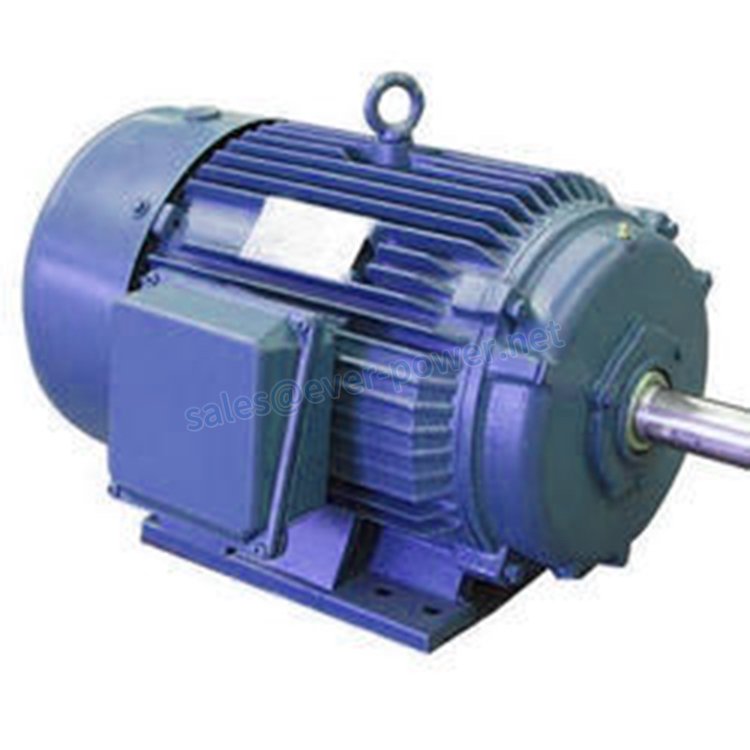
Three-phase motors are more efficient than single phase motors and are commonly found in applications requiring more than 7.5 horsepower. Although the National Electric Code does not specify specific conductor colors for three-phase 3 Phase Induction Motor china current, it is common to use black, red and blue wires to identify lines L1, L2 and L3 respectively. The voltage cycle of each line lags its predecessor by 120 degrees — L2 reaches its peak voltage after L1, and L3 reaches its peak voltage after L2. Two wiring configurations, Wye and Delta, indicate the wiring methods for three-phase motors. These instructions cover a dual voltage, three-phase motor, the most common type.
Step 1
Turn off the power supplying the circuit to be wired to the motor. A three-phase motor must be wired to a three-phase supply.
Step 2
Open the motor wiring box and identify the wires within. The nine wires should be labeled 1 through 9. Some motor leads are identified by color; in this case consult the motor documentation for lead identification.
Step 3
Examine the motor nameplate for wiring information. The nameplate will specify the motor voltages and may give specific wiring information. Many motors can be wired for a high and low voltage and for either Delta or Wye (sometimes called Y or Star wiring). Wire the motor for the appropriate voltage to which you are connecting the motor.
Step 4
Make all wiring connections with wire nuts of the correct size for the conductors being used and the number of conductors being connected together. If there is a neutral wire in the conduit or cable supplying the motor, it is unused for the motor’s three-phase wiring; cap it with a wire nut. For example, use a red wire nut to connect two 12-gauge wires. Hold the bare ends of the conductors together and twist on a wire nut.
Step 5
Swap any two line connections to reverse the motor rotation. For example, move supply line T1 to T2 and supply line T2 to L1  and the motor will reverse direction. You can buy motor control switches to accomplish this change.
Wye Wiring
Step 1
Make the connections for low voltage, 230-volt wiring. Connect motor leads 4, 5 and 6 together. Connect motor leads 7 and 1 with the black L1 conductor. Connect motor leads 8 and 2 with the red L2 conductor. Connect motor leads 9 and 3 with the blue L3 conductor.
Step 2
Make the connections for high voltage, 460-volt wiring. Connect motor leads 6 and 9 together. Connect motor leads 5 and 8 together. Connect motor leads 4 and 7 together. Connect motor lead 1 to the black L1 conductor. Connect motor lead 2 to the red L2 conductor. Connect motor lead 3 to the blue L3 conductor.
Step 3
Connect the ground wire to the motor’s ground terminal. Loosen the ground terminal screw, insert the ground wire into the terminal and tighten the screw firmly. Close the motor’s wiring box.
Delta Wiring
Step 1
Make the connections for low voltage, 230-volt wiring. Connect motor leads 1, 7 and 6 to the black L1 conductor. Connect motor leads 2, 8 and 4 to the red L2 conductor. Connect motor leads 3, 5 and 9 to the blue L3 conductor.
Step 2
Make the connections for high voltage, 460-volt wiring. Connect motor leads 9 and 6 together. Connect motor leads 4 and 7 together. Connect motor leads 8 and 5 together. Connect motor lead 1 to the black L1 conductor. Connect motor lead 2 to the red L2 conductor. Connect motor lead 3 to the blue L3 conductor.
Step 3
Connect the ground wire to the motor’s ground terminal. Loosen the ground terminal screw, insert the ground wire into the terminal and tighten the screw firmly. Close the motor’s wiring box.